XTRAN Example — Combine COBOL Arithmetic Statements
Scenario: You have inherited some old COBOL code that was created by naïve programmers who used a multiplicity of consecutive simplistic arithmetic statements. As a result, it's hard to follow what the code is doing.
XTRAN to the rescue!
The following example uses a set of XTRAN rules ("meta-code") for re-engineering COBOL by searching for situations in the code where consecutive arithmetic statements can be combined, increasing the code's readability.
The rules comprise only 50 code lines of meta-code. They use XTRAN's powerful statement and expression pattern matching and replacement capabilities to automate the re-engineering — two sets of "match" statement patterns and corresponding "replace" statement patterns. The rules iterate through the code until no more replacements can be done. This has the effect that the result of a replacement is then examined for a possible subsequent replacement involving additional statements.
In the patterns below, THIS indicates COBOL elements and
<this> indicates meta
elements.
For matching consecutive ADD statements, we use
a two-statement pattern:
        ADD <expr1> TO <expr2>.
        ADD <expr3> TO <expr2>.
where <exprn> match
any legal expressions, including comma lists of same. Note
that, for the pattern to
match, <expr2> must be the same in
both statements.
The "replace" pattern is a single statement:
ADD <expr1>, <expr3> TO <expr2>.
where <exprn> are whatever
expressions matched the
corresponding <exprn> in the
"match" pattern.
We use similar "match" and "replace"
patterns for consecutive SUBTRACT statements. Similar
patterns can be added for MULTIPLY and DIVIDE
statements.
How can such powerful and generalized re-engineering be automated in only 50 code lines of XTRAN rules? Because there is so much capability already available as part of XTRAN's rules language. The rules used for this example take advantage of the following rules language functionality:
- "Per statement" recursive iterators
- XIR's language-independent properties
- Statement-level pattern matching and replacement in XIR
NOTE that the rendered code shown as XTRAN's output below was done with default conditions; XTRAN provides many options for controlling the way it renders code for output.
The input to and output from XTRAN are untouched.
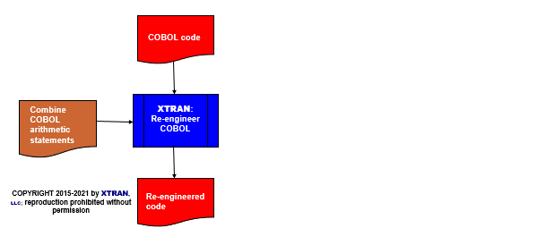
Process Flowchart
Here is a flowchart for this process, in which the elements are color coded:
- BLUE for XTRAN versions (runnable programs)
- ORANGE for XTRAN rules (text files)
- RED for
code

Input to XTRAN:
IDENTIFICATION DIVISION.
SOURCE-COMPUTER. Whiz-Bang 1000.
TARGET-COMPUTER. Whiz-Bang 2000.
DATE-WRITTEN.  07/04/77.
DATE-COMPILED.  05/12/15.
PROGRAM-ID.  DEMCBS-R.

DATA DIVISION.
WORKING-STORAGE SECTION.
        77 VAR1 COMP PIC 9(5)V99.
        77 VAR2 DISPLAY PIC 9(3)V99.
        77 VAR3 COMP-1.
        77 VAR4 COMP.
        77 VAR5 DISPLAY PIC 99.

PROCEDURE DIVISION.
        ADD VAR1 TO VAR3.
        ADD VAR2, VAR4 TO VAR3.
        ADD VAR5 TO VAR3.
        SUBTRACT VAR1 FROM VAR3.
        SUBTRACT VAR2, VAR4 FROM VAR3.
        STOP RUN.
Output from XTRAN:
IDENTIFICATION DIVISION.
SOURCE-COMPUTER. Whiz-Bang 1000.
TARGET-COMPUTER. Whiz-Bang 2000.
DATE-WRITTEN. 07/04/77.
DATE-COMPILED. 05/12/15.
PROGRAM-ID. DEMCBS-R.

DATA DIVISION.
WORKING-STORAGE SECTION.
        77 VAR1 COMP PIC 9(5)V99.
        77 VAR2 DISPLAY PIC 9(3)V99.
        77 VAR3 COMP-1.
        77 VAR4 COMP.
        77 VAR5 DISPLAY PIC 99.

PROCEDURE DIVISION.
        ADD VAR1, VAR2, VAR4, VAR5 TO VAR3.
        SUBTRACT VAR1, VAR2, VAR4 FROM VAR3.
        STOP RUN.
Notation in XTRAN run log
Statement-combining rules combined 3 statements